Function generator or waveform generator is an integral part of electronics and used to produce various kinds of waveforms like a sine wave, square wave, Sawtooth wave, etc. We have already designed sine wave generator circuit, square wave generator circuit, and sawtooth wave generator circuit. Now in this tutorial, we will show you, how to design a triangular waveform generator circuit using Op-amp and few basic components.

A triangle wave consists of a constant rising slope followed by a constant falling slope, and the wave resembles a poorly drawn mountain range.
Triangle wave generators are used in things as diverse as transistor curve tracers, PWM controllers, class D amplifiers, and tone generators.
Parts Required
- 1x LM358 or similar op-amp
- 3x 1K resistors
- 1x 10K resistor
- 1x 100K resistor
- 1x 1nF ceramic capacitor
- 1x 1uF electrolytic capacitor
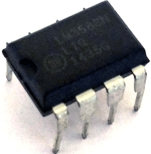
Op-amp LM358
Op-amps are also known as Voltage Comparators. When the voltage at the non-inverting input (+) is higher than the voltage at inverting input (-), then the output of the comparator is High. And if the voltage of inverting input (-) is Higher than the non-inverting end (+), then output is LOW. Know more about the working of op-amp here.

LM358 is a Dual Low Noise Operational Amplifier which has two independent voltage comparators inside. This is a general-purpose op-amp which can be configured in many modes like comparator, summer, integrator, amplifier, differentiator, inverting mode, non- inverting mode, etc. To learn more about LM358 go through LM358 various circuits as amplifier and comparator
Circuit Diagram
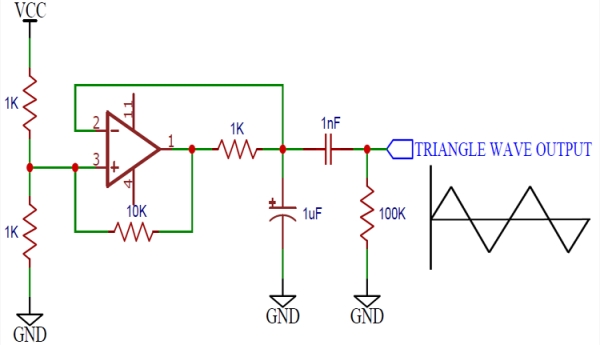
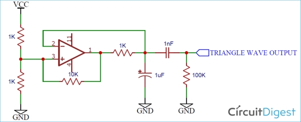
Schematics for Op Amp triangular wave generator is given below:

Working of Triangle Wave Generator
This circuit is a simple example of a relaxation oscillator using a single op-amp as a comparator.

Initially, let us assume that the capacitor is discharged. This puts the inverting input at a voltage lower than the non-inverting input, which is half the supply voltage from the resistor divider.
The output goes high till the capacitor voltage goes above half the supply voltage, at which point the voltage at the inverting input is greater than the non-inverting input. The output then goes low, discharging the capacitor. At the same time, the 10K resistor acts as hysteresis – when the output goes low, the bottom leg of the voltage divider now has a 1K and a 10K in parallel, which decreases the overall resistance and reduces the reference voltage.
The values of the hysteresis resistor and the resistor divider can be changed to increase or decrease the frequency.
The output of the opamp is then AC coupled to produce a signal that has an equal positive and negative swing. This signal can easily be amplified.
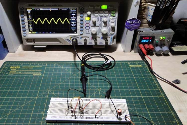
So this is how a simple triangle wave generator can be built using a single Op-amp and few discrete components.
Source: Triangle Wave Generator Circuit using Op-amp
The post Triangle Wave Generator Circuit using Op-amp appeared first on PIC Microcontroller.
from Blog – PIC Microcontroller https://ift.tt/3ip9BfT


No comments:
Post a Comment
Please do not enter any spam link in the comment box.