Project Overview
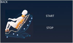
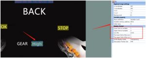
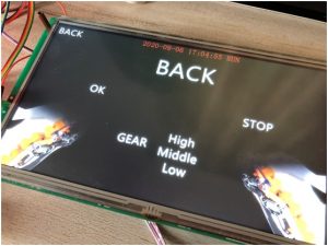
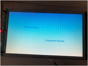
Here we do is a home massage chair application, will STONE TFT After the LCD serial screen is powered on, a start interface will appear. After a short stay, it will jump to a specific interface. This interface is used to set our current time. When setting, a keyboard will pop up. After setting, click OK to enter the massage mode selection interface. Here, I have set three modes: head massage, back massage and comprehensive mode. In the mode, the massage intensity can be set, the high, middle and low gears can be set, and the corresponding LED light will be used for intensity indication; the massage times can also be set, after reaching the set number, it will automatically stop; in the comprehensive mode, the head and back will be massaged at the same time, and it can be turned off when it is not needed. These actions are through the STONE TFT LCD serial port screen to achieve command transmission.
The communication functions are as follows:
① The serial port screen of STONE TFT LCD realizes the function of button switching interface;
② The serial port screen of STONE TFT LCD realizes the function of automatic jump when starting up;
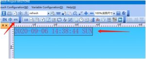
③ The serial port screen of STONE TFT LCD realizes time setting;
④ The serial port screen of STONE TFT LCD realizes data variable distribution;
⑤ STONE TFT LCD serial port screen realizes serial command communication.
⑥ STONE TFT LCD serial port screen realizes the function of menu bar selection;
Modules required for the project:
① STONE TFT LCD;
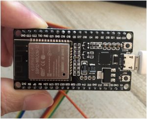
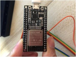
② Arduino ESP32;
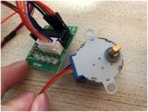
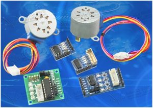
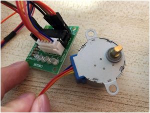
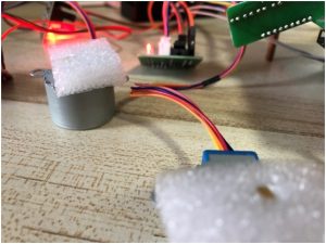
③ Stepper motor drive and module;
④ LED array module;
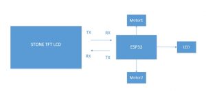
Block diagram:
Hardware introduction and principle
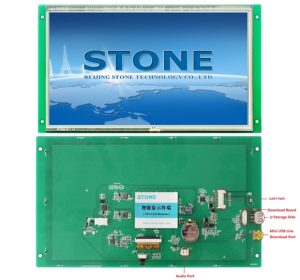
Size: 10.1 inch
Resolution: 1024×600
Brightness: 300cd / m2, LED backlight;
RGB color: 65K;
visual area: 222.7mm * 125.3mm;
working life: 20000 hours. 32-bit cortex-m4 200Hz CPU;
flash memory: 128MB (or 1GB) ;
UART interface: RS232 / RS485 / TTL / USB;
Toolbox software for GUI design, simple and powerful hex instructions.
STVC101WT-01 TFT display module communicates with MCU through serial port, which needs to be used in this project. We only need to add the designed UI picture through the upper computer through the menu bar options to buttons, text boxes, background pictures, and page logic, then generate the configuration file, and finally download it to the display screen to run.
The manual can be downloaded through the official website:
https://www.stoneitech.com/support/download
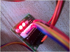
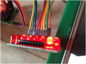
LED array module
Product features
This is a galloping lamp display module with 8 LEDs on board. The external voltage is 3-5.5vdc, and the corresponding LED can be lighted at low level. It is especially suitable for IO test of single chip microcomputer to realize indicator control.
Electrical parameters
-Working voltage: 3 – 5.5VDC
-Working current: 24Ma (maximum)
-Effective level: low level
-Number of LEDs: 8
-Display color: red (D1 / D2 / D3 / D4 / D5 / D6 / D7 / D8)
-It is very suitable for MCU experiment and DIY
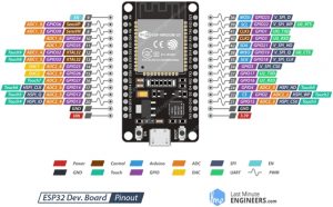
ESP32 EVB
Esp32 is a single-chip scheme integrated with 2.4 GHz WiFi and Bluetooth dual-mode. It adopts TSMC’s ultra-low power consumption 40 nm technology, with ultra-high RF performance, stability, versatility and reliability, as well as ultra-low power consumption, which meets different power consumption requirements and is suitable for various application scenarios.
Wi-Fi
- 802.11 b/g/n
- 802.11 n (2.4 GHz) up to 150 Mbps
- wireless multimedia (WMM)
- frame aggregation (TX / RX A-MPDU, Rx A-MSDU)
- immediate block ACK
- defragmentation
- beacon automatic monitoring (hardware TSF)
- 4x virtual Wi Fi interface
Bluetooth
- Bluetooth v4.2 complete standard, including traditional Bluetooth (BR / EDR) and low power Bluetooth (ble)
- supports standard class-1, class-2 and class-3 without external power amplifier
- enhanced power control
Output power up to +12 dBm
- nzif receiver has – 94 DBM ble reception sensitivity
- adaptive frequency hopping (AFH)
- standard HCI based on SDIO / SPI / UART interface
• high speed UART HCI up to 4 Mbps
Support for Bluetooth 4.2 br / EDR and ble dual-mode controller
- synchronous connection oriented / extended synchronous connection oriented (SCO / ESCO)
- CVSD and SBC audio codec algorithms
- piconet and scatternet
- multi device connection with traditional Bluetooth and low power Bluetooth
- support simultaneous broadcast and scanning
ULN2003 Steeper Motor
Product features
ULN2003 is a Darlington display with high voltage and high current. It consists of seven Silicon NPN Darlington tubes. Each pair of Darlington of ULN2003 is connected in series with a 2.7K base resistor. Under 5V working voltage, it can be directly connected with TTL and CMOS circuit, which can directly process the data that needs standard logic buffer. Here we use DIP-16 package, 4-phase 5-wire 5V stepping motor.
Structure and Application
Development steps
Arduino ESP32
Download IDE
To complete the code development of esp32, Arduino is used to develop and compile. First, you need to install the environment and enter the Arduino official website:
https://www.arduino.cc/en/Main/Software, and download the version for your own platform.
Code
HeadGearHigh is used to set the gear to high in receive head mode
HeadGearMiddle is used to set the gear to middle in receive head mode
HeadGearLow is used to set the gear to low in receive head mode
HeadTiming is used to receive the number of times set in head mode
HeadModeStart is used to start in receive header mode
HeadModeStop is used to stop in receive header mode
BackGearHigh is used to set the gear to high in receive back mode
BackGearMiddle is used to set the gear to middle in receive back mode
BackGearLow is used to set the gear to low in receive back mode
BackModeStart is used to start in receive back mode
BackModeStop is used to stop in receive back mode
IntegratedModeStart is used to receive start in integrated mode
IntegratedModeStop is used to receive stop in integrated mode
After the code is written, we start to compile. After the compilation is successful, download the code to the esp32 EVB board. The operation is as follows:
STONE TOOL 2019
New Project
Find the tool 2019 directory and double-click to open STONE Tool 2019
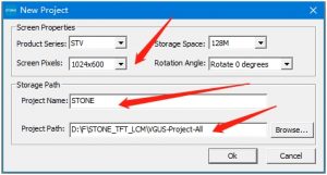
Click new project and make changes to the resolution, project name, and save path.
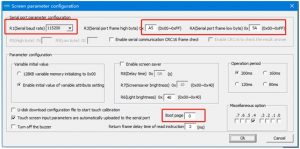
Then set the boot page, and set the communication packet header:
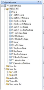
Add picture
By default, there is a blue back image after a new project is created.
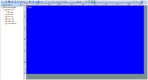
Right click 0.jpg and select remove to delete it. In the same way, select Add to add the image required by the project.
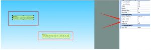
Setting of selection interface
RTC
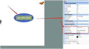
To set the time function, first add a clock setting control.
Add an RTC control.
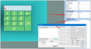
To make input keyboard, we need to add a button control to each array and give the corresponding key value.
Menu bar selection
Add the menu bar control, set the initial value, and add the corresponding ICO library.
Page jump function
You can set the button effect and the switch page, and the switching interface effect of other buttons is also similar.
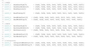
Key command setting
Each button needs to be given corresponding action, so the following settings are made:
//HEAD
uint8_t HeadGearHigh[9] = {0xA5, 0x5A, 0x06, 0x83, 0x00, 0x0E, 0x01, 0x00, 0x03};
uint8_t HeadGearMiddle[9] = {0xA5, 0x5A, 0x06, 0x83, 0x00, 0x0E, 0x01, 0x00, 0x02};
uint8_t HeadGearLow[9] = {0xA5, 0x5A, 0x06, 0x83, 0x00, 0x0E, 0x01, 0x00, 0x01};
uint8_t HeadTiming[9] = {0xA5, 0x5A, 0x06, 0x83, 0x00, 0x11, 0x01, 0x00, 0x09};
uint8_t HeadModeStart[9] = {0xA5, 0x5A, 0x06, 0x83, 0x00, 0x19, 0x01, 0x41, 0x61};
uint8_t HeadModeStop[9] = {0xA5, 0x5A, 0x06, 0x83, 0x00, 0x24, 0x01, 0x46, 0x66};
//BACK
uint8_t BackGearHigh[9] = {0xA5, 0x5A, 0x06, 0x83, 0x00, 0x1A, 0x01, 0x00, 0x01};
uint8_t BackGearMiddle[9] = {0xA5, 0x5A, 0x06, 0x83, 0x00, 0x1A, 0x01, 0x00, 0x02};
uint8_t BackGearLow[9] = {0xA5, 0x5A, 0x06, 0x83, 0x00, 0x1A, 0x01, 0x00, 0x03};
uint8_t BackModeStart[9] = {0xA5, 0x5A, 0x06, 0x83, 0x00, 0x0C, 0x01, 0x42, 0x62};
uint8_t BackModeStop[9] = {0xA5, 0x5A, 0x06, 0x83, 0x00, 0x0D, 0x01, 0x43, 0x63};
//Integrated
uint8_t IntegratedModeStart[9]= {0xA5, 0x5A, 0x06, 0x83, 0x00, 0x0F, 0x01, 0x44, 0x64};
uint8_t IntegratedModeStop[9] = {0xA5, 0x5A, 0x06, 0x83, 0x00, 0x1F, 0x01, 0x45, 0x65};
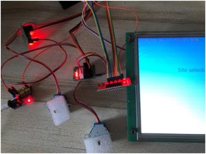
Connection

Code
/*
Stepper Motor Control – one revolution
This program drives a unipolar or bipolar stepper motor.
The motor is attached to digital pins 8 – 11 of the Arduino.
The motor should revolve one revolution in one direction, then
one revolution in the other direction.
Created 11 Mar. 2007
Modified 30 Nov. 2009
by Tom Igoe
*/
//#include <Stepper.h>
#include “stdlib.h”
#include <AccelStepper.h>
const float STEPCYCLE = 2050;//A Cycle by Step is 2050;
// myStepper.setSpeed(100);//5V, it can be set up to 180
const float TheMaxSpeed = 1000.0; // change this to fit the number of steps per revolution
const float headspeed_str[4] =
{
0,
TheMaxSpeed / 4,
TheMaxSpeed / 2,
TheMaxSpeed,
};
const float backspeed_str[4] =
{
0,
TheMaxSpeed,
TheMaxSpeed / 2,
TheMaxSpeed / 4,
};
// for your motor
// initialize the stepper library on pins 8 through 11:
AccelStepper HeadStepper(AccelStepper::FULL4WIRE, 15, 0, 2, 4);//The middle two IO are reversed
AccelStepper BackStepper(AccelStepper::FULL4WIRE, 16, 5, 17, 18);//The middle two IO are reversed
const int ledPin_1 = 14; // the number of the LED pin
const int ledPin_2 = 27; // the number of the LED pin
const int ledPin_3 = 26; // the number of the LED pin
const int ledPin_4 = 25; // the number of the LED pin
const int ledPin_5 = 33; // the number of the LED pin
const int ledPin_6 = 21; // the number of the LED pin
const int ledPin_7 = 22; // the number of the LED pin
const int ledPin_8 = 23; // the number of the LED pin
//buf
uint8_t cout_i = 0;
uint8_t RecievedTemp[9] = {0};
float settingbuf[2] = {TheMaxSpeed, 0};
float MorenCycle = 100;
//HEAD
uint8_t HeadGearHigh[9] = {0xA5, 0x5A, 0x06, 0x83, 0x00, 0x0E, 0x01, 0x00, 0x03};
uint8_t HeadGearMiddle[9] = {0xA5, 0x5A, 0x06, 0x83, 0x00, 0x0E, 0x01, 0x00, 0x02};
uint8_t HeadGearLow[9] = {0xA5, 0x5A, 0x06, 0x83, 0x00, 0x0E, 0x01, 0x00, 0x01};
uint8_t HeadTiming[9] = {0xA5, 0x5A, 0x06, 0x83, 0x00, 0x11, 0x01, 0x00, 0x09};
uint8_t HeadModeStart[9] = {0xA5, 0x5A, 0x06, 0x83, 0x00, 0x19, 0x01, 0x41, 0x61};
uint8_t HeadModeStop[9] = {0xA5, 0x5A, 0x06, 0x83, 0x00, 0x24, 0x01, 0x46, 0x66};
//BACK
uint8_t BackGearHigh[9] = {0xA5, 0x5A, 0x06, 0x83, 0x00, 0x1A, 0x01, 0x00, 0x01};
uint8_t BackGearMiddle[9] = {0xA5, 0x5A, 0x06, 0x83, 0x00, 0x1A, 0x01, 0x00, 0x02};
uint8_t BackGearLow[9] = {0xA5, 0x5A, 0x06, 0x83, 0x00, 0x1A, 0x01, 0x00, 0x03};
uint8_t BackModeStart[9] = {0xA5, 0x5A, 0x06, 0x83, 0x00, 0x0C, 0x01, 0x42, 0x62};
uint8_t BackModeStop[9] = {0xA5, 0x5A, 0x06, 0x83, 0x00, 0x0D, 0x01, 0x43, 0x63};
//Integrated
uint8_t IntegratedModeStart[9]= {0xA5, 0x5A, 0x06, 0x83, 0x00, 0x0F, 0x01, 0x44, 0x64};
uint8_t IntegratedModeStop[9] = {0xA5, 0x5A, 0x06, 0x83, 0x00, 0x1F, 0x01, 0x45, 0x65};
void setup()
{
//Serial port initialization
Serial.begin(115200);
//The motor starts running separately
// HeadStepper_Setting_Run(TheMaxSpeed, 5);
// BackStepper_Setting_Run(TheMaxSpeed, 5);
// initialize the LED pin as an output:
pinMode(ledPin_1, OUTPUT);
pinMode(ledPin_2, OUTPUT);
pinMode(ledPin_3, OUTPUT);
pinMode(ledPin_4, OUTPUT);
pinMode(ledPin_5, OUTPUT);
pinMode(ledPin_6, OUTPUT);
pinMode(ledPin_7, OUTPUT);
pinMode(ledPin_8, OUTPUT);
digitalWrite(ledPin_1, HIGH); // turn the LED on (HIGH is the voltage level)
digitalWrite(ledPin_2, HIGH); // turn the LED on (HIGH is the voltage level)
digitalWrite(ledPin_3, HIGH); // turn the LED on (HIGH is the voltage level)
digitalWrite(ledPin_4, HIGH); // turn the LED on (HIGH is the voltage level)
digitalWrite(ledPin_5, HIGH); // turn the LED on (HIGH is the voltage level)
digitalWrite(ledPin_6, HIGH); // turn the LED on (HIGH is the voltage level)
digitalWrite(ledPin_7, HIGH); // turn the LED on (HIGH is the voltage level)
digitalWrite(ledPin_8, HIGH); // turn the LED on (HIGH is the voltage level)
}
void loop()
{
if(Serial.available() != 0)
{
for(cout_i = 0; cout_i < 9; cout_i ++)
{
RecievedTemp[cout_i] = Serial.read();
}
// if(HeadStepper.isRunning() == true)
// {
// HeadStepper.stop();
// }
// if(BackStepper.isRunning() == true)
// {
// BackStepper.stop();
// }
// else
// {
// Stepper2_Setting_Run(TheMaxSpeed, 5);
// }
// Serial.write(RecievedTemp, 9);
switch(RecievedTemp[5])
{
case 0x0E://head gear
if(HeadStepper.isRunning() == true)
{
HeadStepper.stop();
}
settingbuf[0] = headspeed_str[RecievedTemp[8]];
if(RecievedTemp[8] == 1)
{
digitalWrite(ledPin_1, LOW); // turn the LED on (HIGH is the voltage level)
digitalWrite(ledPin_2, LOW); // turn the LED on (HIGH is the voltage level)
digitalWrite(ledPin_3, LOW); // turn the LED on (HIGH is the voltage level)
digitalWrite(ledPin_4, HIGH); // turn the LED on (HIGH is the voltage level)
digitalWrite(ledPin_5, HIGH); // turn the LED on (HIGH is the voltage level)
digitalWrite(ledPin_6, HIGH); // turn the LED on (HIGH is the voltage level)
digitalWrite(ledPin_7, HIGH); // turn the LED on (HIGH is the voltage level)
digitalWrite(ledPin_8, HIGH); // turn the LED on (HIGH is the voltage level)
}
else if(RecievedTemp[8] == 2)
{
digitalWrite(ledPin_1, LOW); // turn the LED on (HIGH is the voltage level)
digitalWrite(ledPin_2, LOW); // turn the LED on (HIGH is the voltage level)
digitalWrite(ledPin_3, LOW); // turn the LED on (HIGH is the voltage level)
digitalWrite(ledPin_4, LOW); // turn the LED on (HIGH is the voltage level)
digitalWrite(ledPin_5, LOW); // turn the LED on (HIGH is the voltage level)
digitalWrite(ledPin_6, LOW); // turn the LED on (HIGH is the voltage level)
digitalWrite(ledPin_7, HIGH); // turn the LED on (HIGH is the voltage level)
digitalWrite(ledPin_8, HIGH); // turn the LED on (HIGH is the voltage level)
}
else
{
digitalWrite(ledPin_1, LOW); // turn the LED on (HIGH is the voltage level)
digitalWrite(ledPin_2, LOW); // turn the LED on (HIGH is the voltage level)
digitalWrite(ledPin_3, LOW); // turn the LED on (HIGH is the voltage level)
digitalWrite(ledPin_4, LOW); // turn the LED on (HIGH is the voltage level)
digitalWrite(ledPin_5, LOW); // turn the LED on (HIGH is the voltage level)
digitalWrite(ledPin_6, LOW); // turn the LED on (HIGH is the voltage level)
digitalWrite(ledPin_7, LOW); // turn the LED on (HIGH is the voltage level)
digitalWrite(ledPin_8, LOW); // turn the LED on (HIGH is the voltage level)
}
break;
case 0x11://head timing
if(HeadStepper.isRunning() == true)
{
HeadStepper.stop();
}
settingbuf[1] = RecievedTemp[8];
break;
case 0x19://head start
if(settingbuf[1] == 0)
{
settingbuf[1] = 5;
}
break;
case 0x24://head stop
if(HeadStepper.isRunning() == true)
{
HeadStepper.stop();
}
break;
case 0x1A://backgear
if(BackStepper.isRunning() == true)
{
BackStepper.stop();
}
settingbuf[0] = backspeed_str[RecievedTemp[8]];
if(RecievedTemp[8] == 3)
{
digitalWrite(ledPin_1, LOW); // turn the LED on (HIGH is the voltage level)
digitalWrite(ledPin_2, LOW); // turn the LED on (HIGH is the voltage level)
digitalWrite(ledPin_3, LOW); // turn the LED on (HIGH is the voltage level)
digitalWrite(ledPin_4, HIGH); // turn the LED on (HIGH is the voltage level)
digitalWrite(ledPin_5, HIGH); // turn the LED on (HIGH is the voltage level)
digitalWrite(ledPin_6, HIGH); // turn the LED on (HIGH is the voltage level)
digitalWrite(ledPin_7, HIGH); // turn the LED on (HIGH is the voltage level)
digitalWrite(ledPin_8, HIGH); // turn the LED on (HIGH is the voltage level)
}
else if(RecievedTemp[8] == 2)
{
digitalWrite(ledPin_1, LOW); // turn the LED on (HIGH is the voltage level)
digitalWrite(ledPin_2, LOW); // turn the LED on (HIGH is the voltage level)
digitalWrite(ledPin_3, LOW); // turn the LED on (HIGH is the voltage level)
digitalWrite(ledPin_4, LOW); // turn the LED on (HIGH is the voltage level)
digitalWrite(ledPin_5, LOW); // turn the LED on (HIGH is the voltage level)
digitalWrite(ledPin_6, LOW); // turn the LED on (HIGH is the voltage level)
digitalWrite(ledPin_7, HIGH); // turn the LED on (HIGH is the voltage level)
digitalWrite(ledPin_8, HIGH); // turn the LED on (HIGH is the voltage level)
}
else
{
digitalWrite(ledPin_1, LOW); // turn the LED on (HIGH is the voltage level)
digitalWrite(ledPin_2, LOW); // turn the LED on (HIGH is the voltage level)
digitalWrite(ledPin_3, LOW); // turn the LED on (HIGH is the voltage level)
digitalWrite(ledPin_4, LOW); // turn the LED on (HIGH is the voltage level)
digitalWrite(ledPin_5, LOW); // turn the LED on (HIGH is the voltage level)
digitalWrite(ledPin_6, LOW); // turn the LED on (HIGH is the voltage level)
digitalWrite(ledPin_7, LOW); // turn the LED on (HIGH is the voltage level)
digitalWrite(ledPin_8, LOW); // turn the LED on (HIGH is the voltage level)
}
break;
case 0x0C://backstart
BackStepper_Setting_Run(settingbuf[0], MorenCycle);
break;
case 0x0D://backstop
if(BackStepper.isRunning() == true)
{
BackStepper.stop();
}
break;
case 0x0F://integratestart
if(HeadStepper.isRunning() == true)
{
HeadStepper.stop();
}
if(BackStepper.isRunning() == true)
{
BackStepper.stop();
}
break;
case 0x1F://integratedstop
if(HeadStepper.isRunning() == true)
{
HeadStepper.stop();
}
if(BackStepper.isRunning() == true)
{
BackStepper.stop();
}
break;
default:
break;
}
// Serial.write(&Targetvalue, 1);
// Serial.print(Targetvalue);
}
}
Application of massage chair Appendix
The post Using STONE LCD screen and ESP32 MCU to implement home massage chair application appeared first on PIC Microcontroller.
from Blog – PIC Microcontroller https://ift.tt/36iP22r


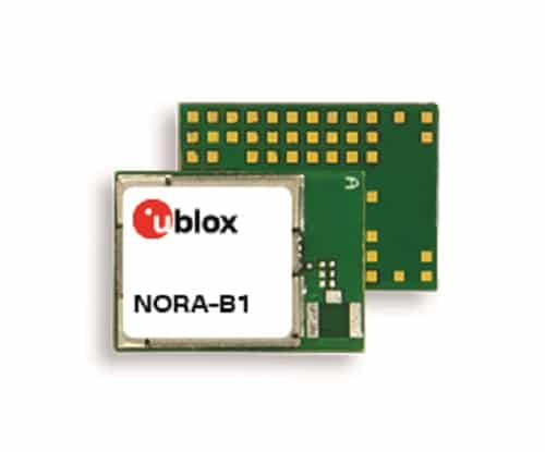 The Bluetooth module from u-blox is based on an Arm Cortex M33 dual-core MCU, making it optimal for handling applications such as industrial and smart buildings It provides cryptography and delivers root of trust and secure key storage u-blox has announced the launch of the NORA-B1 Bluetooth module, the newest member in the company’s short-range […]
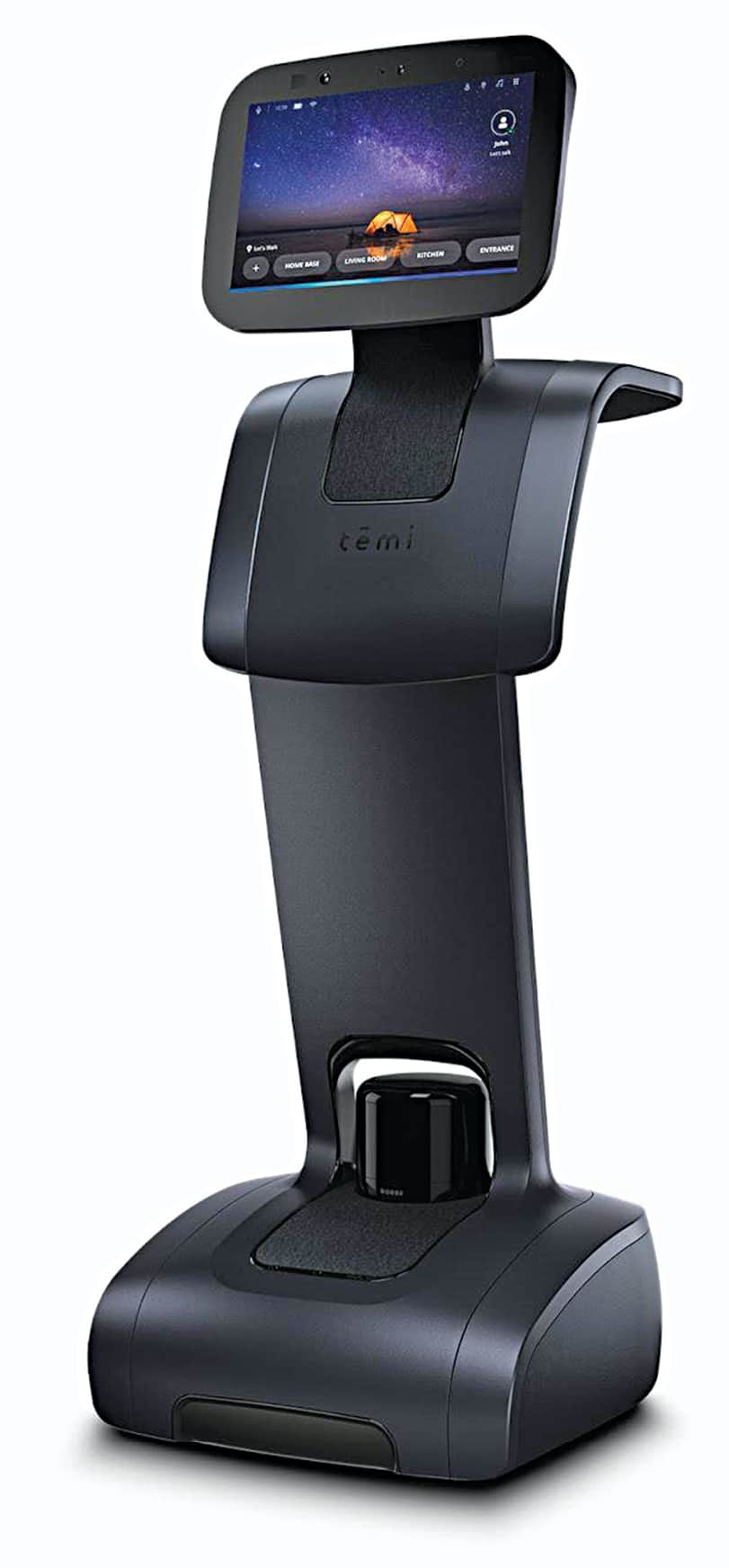 Robots, though initially used for purposes like manufacturing in factories, are slowly finding their way more often in workplaces and homes for day-to-day work. After realising how troublesome it can be for older people to perform basic tasks with their own hands, Yossi Wolf, co-founder of Roboteam, designed the autonomous personal artificial intelligence (AI) assistant […]


 Flex Power Modules’ new DC-DC converter series provides complete monitoring functionality and feedback loop control to help stabilisation It has a high-efficiency feature while allowing configuration of several electrical aspects of the device Flex Power Modules has launched the BMR683, a new series of digital PMBus DC-DC converters that provide indispensable monitoring functionality and control […]
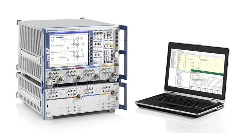 Rohde & Schwarz’s new test and measurement solutions for TRM performance validation enables the customer to maximize their radar system capabilities The TRM radar test system delivers fast possible speeds, helping to drastically reduce the test time Modern active electronically scanned array (AESA) radars are an essential part of the global aerospace and defence industry. […]
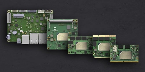 congatec’s launch of low-power processors provide a great computing power and double graphics performance The processors are perfect for any non-real-time application as they offer numerous features and functions essential for today’s edge-connected embedded systems congatec has launched Intel’s new low-power processor generation on five embedded form factors. To be made available on SMARC, Qseven, […]
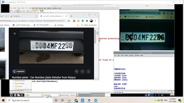 Managing the entry and exit of cars in parking lots is a difficult job. It becomes even more complicated when one wishes to keep track of them using details such as date, time and number plate. Often a dedicated staff is required who can check these details and do data entry. So today we will […]
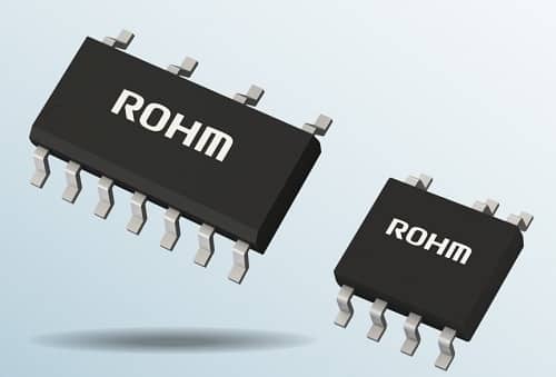 ROHM’s new IC series delivers low standby power and improves communication reliability in home appliances Designers can now eliminate any complex design using discrete components and at the same time, remove the integration of photocouplers The demand for smart appliances and IoT applications is on the rise, having added communication functionality (i.e. Wi-Fi) to home […]