
Efficiency is the name of the game these days, and the SparkFun QC team is all about it! We have successfully deployed a new test-fixture we are calling the “Qwiic Test-bed” and I am here to tell you all about it.
If you are new to SparkFun or haven’t stopped by for a while, you may not be aware of our Qwiic line of products, if so, check out this Qwiic explainer. Being a high variation electronics manufacturer, we in QC keep very busy designing testing hardware and software for new SparkFun originals. We are always trying to find and take advantage of efficiency gains to increase the bandwidth of our three-person team, and the new Qwiic Test-bed does just that. Below is a brief overview of the reasoning, technical details and results of developing with our new test-fixture.

The Motivation:
We wanted to find a way that we, as a team, could increase our bandwidth by saving time developing. Typically we design a test-bed for a product, and that test-bed is only used to test that individual product. This means for each new product we have to: design new testing hardware, build the new test-fixtures, write the software to control the test-fixture and test the product, and maintain the test-fixture through ongoing Production use.
One of the easiest steps we can take to save time during our hardware design process is to repurpose past design files and make modifications to suit your current application, and the same can be done for testing software. But even with these efficiency gains we can’t outrun the turnaround time on test-fixture hardware. What we needed was a physical test-fixture that could be reused to test new products while still supporting the old.
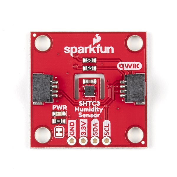
The key to making this test-fixture possible was in part due to the standardization in form factor and pinout of the Qwiic breakout boards, and in part due to all of the boards utilizing the I2C communication protocol. One hard standard was set in regards to form-factor, this standard dictates the ordering of the four essential plated through holes (PTHs): ground (GND), power (VCC), I2C data (SDA), and I2C clock (SCL) (they must also be adjacent).
It should be said that this test-bed was never intended to be able to test every Qwiic breakout board, we just want to capture the majority - some designs just need to break the standard for one reason or another, and trying to design a fixture around all the imaginable deviations would have caused too much scope creep.
The point of the exercise was to expedite as much of the development process as possible when using the Qwiic Test-bed. We opted to use a collaborative firmware sketch that runs on the test-bed, allowing us to build on the test-bed firmware by easily adding new product source files and testing functions required to test new designs. This meant that we could now use the same physical test-fixtures to test multiple assemblies, thus saving time on building up hardware for each new design. By removing the need to design and assemble a physical fixture we’ve saved a bunch of our team’s time, and also allowed the product cycle to move quicker. As an added bonus, the fixture can also be used during the prototyping phase to test new hardware and software.
Hardware:
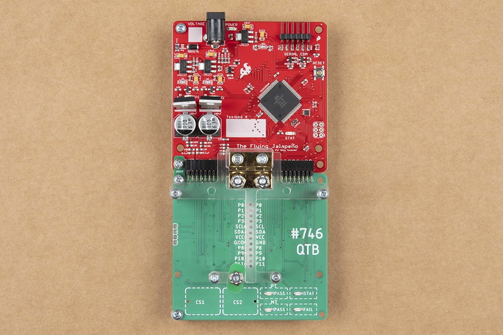
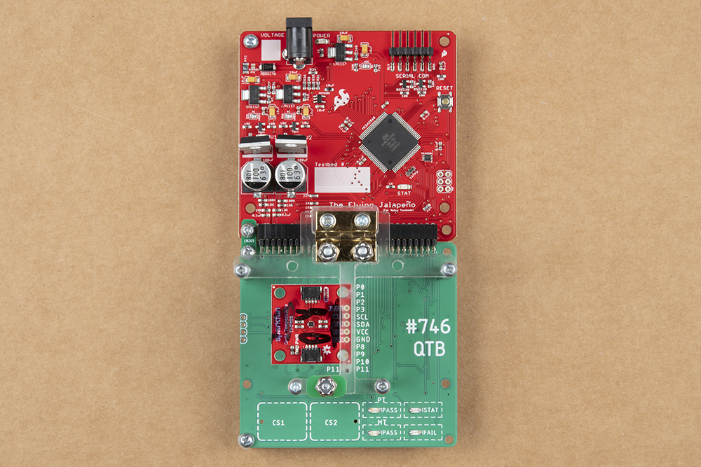
The Qwiic test-bed utilizes pogopins to make a temporary connection to the board’s PTHs while the board is held in place by the hinged acrylic bar on the top. A small nubbin can be spun to keep the bar clamped on the board during testing, or the user can manually hold the bar down. The processing and testing peripherals for the test-fixture are handled by our original testing development board called the “Flying Jalapeno.” Check out Pete’s posts about the development of the Flying Jalapeno here:
- Enginursday: Innovative Testbed Design (Part 1 of 2)
- Enginursday: Innovative Testbed Design (Part 2 of 2)
The test-fixture has two available capacitive sensor pads, four LEDs, and available serial debug for the user to interface with.
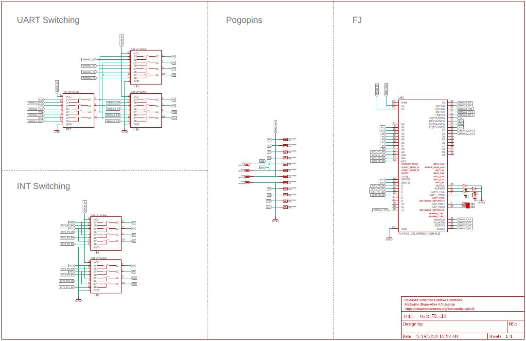
The fixture centers around the four main pogopins: GND, VCC, SDA and SCL, which are separated by a standard 100 mil spacing. Because many of these assemblies break out other signals such as interrupts, enables, analogs, PPMs, clocks and serial RX/TX, the four essential signal pogopins are straddled by eight extra pogopins - four above and four below. Five 74LVC4066 quad switches route the most functionally capable pins from the Flying Jalapeno’s ATmega2560 to the eight extra pogopins, giving the developer the ability to select which pins of the 2560 to connect to the test-board’s signals, and which to disconnect.
By making the acrylic mating surface for the PTH connections slim, a test-board can be placed on either side of the mating area to suit any PTH header orientation. Alignment is facilitated by matching the silk of the test-board with that of the test-bed. In most scenarios, the assembly being tested has fewer PTHs than the test-bed has pogopins; when a pogopin is not being used it’s pushed down by the PCB and separated from any signal by the mask. Reports about usage from our Production department have been positive, and the hardware is holding up well.
Results:
As a whole we’ve been very pleased with the results of using this test-fixture. The three of us in QC are getting a lesson in software collaboration, but with a few rules implemented, co-development has gone smoothly. As a rough calculation, the testing development process for the boards being tested with the Qwiic Test-bed took about 25 percent of the time they would have previously, and with all the projects in the pipes, saving any amount of time is welcomed.
from SparkFun: Commerce Blog https://ift.tt/2zaHrF8


No comments:
Post a Comment
Please do not enter any spam link in the comment box.