
A rectifier is a circuit that converts alternating current (AC) to Direct current (DC). An alternating current always changes its direction over time, but the direct current flows continuously in one direction. In a typical rectifier circuit, we use diodes to rectify AC to DC. But this rectification method can only be used if the input voltage to the circuit is greater than the forward voltage of the diode which is typically 0.7V. We previously explained diode-based half-wave rectifier and full-wave rectifier circuit.
To overcome this issue, the Precision Rectifier Circuit was introduced. The precision rectifier is another rectifier that converts AC to DC, but in a precision rectifier we use an op-amp to compensate for the voltage drop across the diode, that is why we are not losing the 0.6V or 0.7V voltage drop across the diode, also the circuit can be constructed to have some gain at the output of the amplifier as well.
So, in this tutorial, I am going to show you how you can build, test, apply, and debug a precision rectifier circuit using op-amp. Alongside that, I will be discussing some pros and cons of this circuit as well. So, without further ado, let’s get started.
What is a Precision Rectifier Circuit?
Before we know about the Precision Rectifier Circuit, let’s clarify the basics of the rectifier circuit.
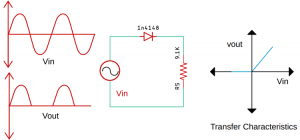
The above figure shows the characteristics of an ideal rectifier circuit with its transfer characteristics. This implies when the input signal is negative, the output will be zero volts and when the input signal is positive the output will follow the input signal.
The above figure shows a practical rectifier circuit with its transfer characteristics. In a practical rectifier circuit, the output waveform will be 0.7 volts less than the applied input voltage, and the transfer characteristic will look like the figure shown in the diagram. At this point, the diode will only conduct if the applied input signal is slightly greater than the forward voltage of the diode.
Now the basics out of the way, let’s turn our focus back to the precision rectifier circuit.
Working of Precision Rectifier
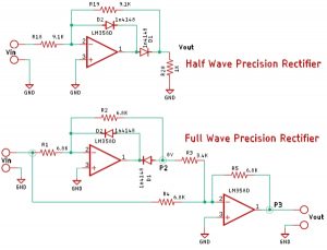
The above circuit shows a basic, half-wave precision rectifier circuit with an LM358 Op-Amp and a 1n4148 diode. To learn how an op-amp works, you can follow this op-amp circuit.
The above circuit also shows you the input and output waveform of the precision rectifier circuit, which is exactly equal to the input. That’s because we are taking the feedback from the output of the diode and the op-amp compensates for any voltage drop across the diode. So, the diode behaves like an ideal diode.
Now in the above image, you can clearly see what happens when a positive and a negative half cycle of the input signal is applied in the input terminal of the Op-Amp. The circuit also shows the transfer characteristics of the circuit.
But in a practical circuit, you will not get the output as shown in the above figure, let me tell you why?
In my oscilloscope, the yellow signal in the input, and the green signal is the output. Instead of getting a half-wave rectification, we are getting a sort of full-wave rectification.
The above image shows you when the diode is off, the negative half cycle is of the signal flows through the resistor on to the output, and that is why we are getting the full-wave rectification like the output, but this is not the actual case.
Let’s see what happens when we connect a 1K load.
Source: Half Wave and Full Wave Precision Rectifier Circuit using Op-Amp
The post Half Wave and Full Wave Precision Rectifier Circuit using Op-Amp appeared first on PIC Microcontroller.
from Blog – PIC Microcontroller https://ift.tt/3jkgxfy


No comments:
Post a Comment
Please do not enter any spam link in the comment box.